"5-axis" gets thrown around like it means one thing. It does not. There is a real, practical gap between 3+2 positional machining, where the rotaries lock at an angle and the part cuts like a 3-axis job, and full simultaneous 5-axis, where all five axes move together while the tool is in the cut. They solve different problems, they carry different price tags, and they live in different software tiers. If your shop is sizing up a trunnion machine, a rotary table, or just the right CAM seat, knowing which one your parts actually demand is the difference between a fast payback and an expensive capability you rarely touch. Here is what each buys you on the floor.
3+2 vs 5-axis, quickly
3+2 (also called 3 plus 2 or positional/indexed) locks the rotary axes at a fixed angle, then cuts with normal X, Y, Z moves. It reaches multi-sided features in one setup and lets you run shorter, stiffer tools. Simultaneous 5-axis moves all five axes at once while cutting, which you need for impellers, blades, and organic blends. SOLIDWORKS CAM Professional handles 3+2 indexing. True simultaneous 5-axis is a CAMWorks Premium capability, not part of SOLIDWORKS CAM.

What 3+2 positional machining really is
In 3+2, your rotary and tilt axes (the A and C, or B and C, depending on the machine) move the part to a position and then lock. From that point on the spindle is doing ordinary 3-axis work in X, Y, and Z. The two extra axes are not cutting. They are orienting. That is why people call it positional or indexed machining: you index to an angle, clamp, and cut.
This sounds modest, but it changes how a part flows through the shop. A block that used to need five separate vise setups, with all the re-indicating and stack-up error that comes with each one, can often be done in one. You fixture the raw stock once, and the machine rotates to present every face and angled boss to the spindle.
Why shops move to 3+2 first
- Reach angled features without re-fixturing. Drilled holes on a compound angle, a pocket on a chamfered face, a port that enters at 30 degrees: the table tilts the work so the tool approaches square. No angle plates, no sine vise gymnastics.
- Shorter tools, more rigidity, better finish. Instead of reaching down into a deep cavity with a long, whippy end mill, you tilt the part and use a short tool close to the holder. Shorter stickout means less deflection, less chatter, faster feeds, and a cleaner wall finish.
- Fewer setups, fewer errors. Every time a part comes out of a fixture and goes back in, you stack tolerance. Consolidating five setups into one or two protects your true position and your scrap rate.
- Better tool access and collision clearance. Orienting the part can pull the holder away from tall walls and clamps that would otherwise be in the way.
For a large share of prismatic parts, brackets, manifolds, housings, fixtures, and mold bases, 3+2 is the whole answer. You are not cutting sculpted surface; you are reaching flat and prismatic features that simply happen to point in different directions.
Where 3+2 lives: SOLIDWORKS CAM Professional
SOLIDWORKS CAM is included with your SOLIDWORKS seat and is powered by CAMWorks. The Professional tier adds 4- and 5-axis indexing, which is the engine behind 3+2 positional work, on top of the 2.5- and 3-axis milling in Standard. So if your goal is to tilt the part, lock it, and machine angled and multi-sided features in a single setup, SOLIDWORKS CAM Professional covers it. If you want the full breakdown of the tiers, see the guide on SOLIDWORKS CAM Standard vs Professional.
Two things make this practical day to day. First, the TechDB stores your tooling, feeds, speeds, and machining strategies so the same angled feature gets programmed the same way every time. Second, your post processor has to output the correct rotary positioning and work-plane codes for your specific control, whether that is a Haas trunnion, a DMG MORI, or a Fanuc-based machine. A post that does not match your kinematics will hand you bad angles, so this is not a place to guess.
Not sure whether 3+2 covers your part mix, or whether the geometry on your prints genuinely demands simultaneous 5-axis? The line runs through your actual parts and your machine's kinematics, and getting it right before you buy is the difference between a fast payback and idle capability.
Get a QuoteWhat simultaneous 5-axis adds
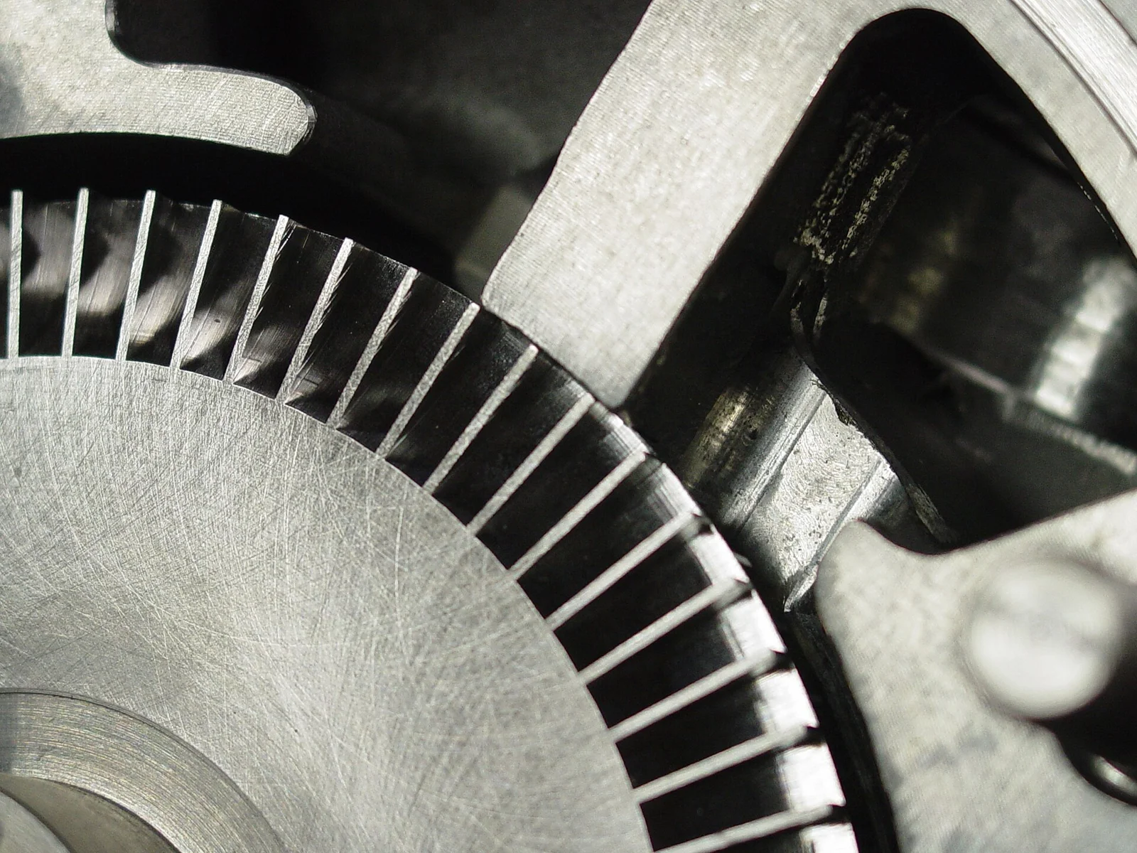
Simultaneous 5-axis is a different animal. Here all five axes move at the same time while the tool is cutting. The tool tip follows a curved path through space and the part keeps rotating and tilting to keep the cutter at the right lead and tilt angle to the surface. This is what lets you flank-mill a twisted blade, finish the curved passage between impeller vanes, or hold a constant contact angle across a freeform blend.
You reach for true 5-axis when the geometry demands it:
- Impellers and blisks with overlapping, curved vanes that a fixed angle cannot reach.
- Turbine and compressor blades where the surface twists along its length.
- Organic and sculpted shapes, medical and aerospace contours, where the tool must stay tangent to a continuously changing surface.
- Port and cavity work where the only collision-free path is one that keeps reorienting the tool as it travels.
Simultaneous 5-axis also leans hard on automatic collision avoidance, because with the tool, holder, part, and fixture all moving relative to each other, you cannot eyeball clearance. The toolpath has to tilt the tool away from gouges on its own.
Where simultaneous 5-axis lives: CAMWorks
Here is the part that trips shops up. Full simultaneous 5-axis machining is not part of SOLIDWORKS CAM. SOLIDWORKS CAM Professional tops out at 4- and 5-axis indexing, which is your 3+2 positional work. For continuous, all-axes-moving toolpaths you step up to CAMWorks, the standalone product SOLIDWORKS CAM is built from, at its Premium tier. Same family, same look and feel, more capability. Your feature knowledge, your TechDB, and your SOLIDWORKS models all carry over, so the move up is an expansion, not a rip-and-replace. If you are weighing where SOLIDWORKS CAM ends and a dedicated package begins, the breakdown of SOLIDWORKS CAM vs CAMWorks vs Mastercam lays out the tiers side by side.
| Consideration | 3+2 (positional) | Simultaneous 5-axis |
|---|---|---|
| Axis motion while cutting | 3 axes (X, Y, Z); rotaries locked | All 5 axes move together |
| Best for | Prismatic and angled features, multi-sided parts | Impellers, blades, twisted and organic surfaces |
| Tool length | Shorter, stiffer tools close to the holder | Often longer reach with controlled tilt |
| Programming complexity | Moderate; index, lock, machine | High; lead/tilt, surface control, collision avoidance |
| Software | SOLIDWORKS CAM Professional | CAMWorks Premium |
| Typical machine | Trunnion, rotary table, indexer, tilt-rotary | True 5-axis trunnion or head-head with continuous control |
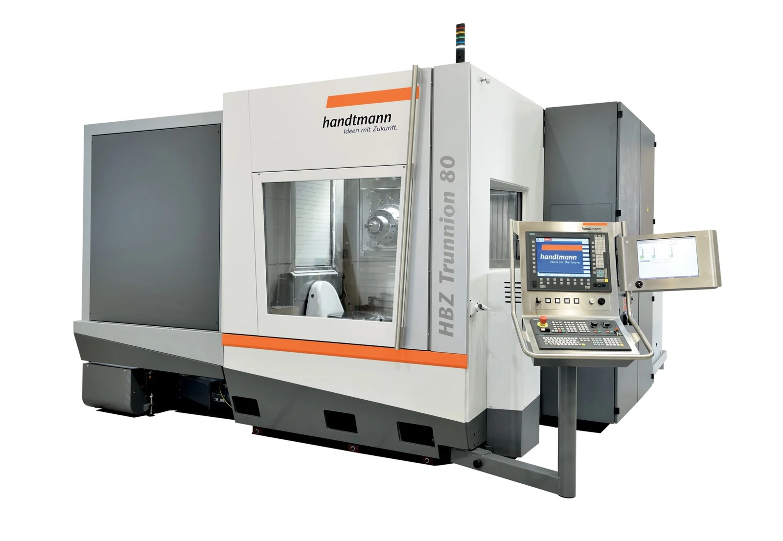
Machines: trunnions, rotary tables, and indexers
The hardware matters as much as the software. A simple rotary table or 4th-axis indexer gets you positional work on one extra axis. A tilt-rotary or trunnion table adds the tilt, giving you the two rotary axes you need for 3+2 on most part faces. The same trunnion machine can often run both 3+2 and simultaneous 5-axis; the difference is whether the control is moving those rotaries during the cut and whether your CAM can program it. Buying a 5-axis-capable machine does not automatically mean you are doing 5-axis work. Plenty of shops run a true 5-axis trunnion almost entirely in 3+2, and that is a perfectly good use of it.
When 3+2 is enough, and when it is not
Be honest about your parts. If your work is brackets, housings, manifolds, fixtures, and mold bases, features that are flat or prismatic but point in different directions, 3+2 in SOLIDWORKS CAM Professional will likely cover the vast majority of it and pay for itself in saved setups and better finishes. I have watched a hydraulic manifold that used to eat five separate vise setups, with a re-indicate between each one, collapse onto a single trunnion fixture, and the scrap that came from stack-up on true position basically disappeared along with the re-fixturing, none of it needing a single axis to move during the cut. The jump to simultaneous 5-axis is justified when you genuinely cannot reach the surface with a locked tool, or when a continuous tangent path is the only way to get the finish and cycle time you need. That means true sculpted geometry: impellers, blades, organic contours.
Many shops land on a sensible path: start with 3+2 to consolidate setups and tighten tolerances, then add simultaneous 5-axis later if and when the part mix demands it. There is no rule that says you must own the most capable toolpath before you benefit from multi-axis.
Matching the tier to the parts on your floor
The trap is buying motion you never cut, or worse, buying a 5-axis-capable machine and then having no CAM seat that can program it past 3+2. Getting it right means lining up three things: the kinematics of your actual trunnion or rotary, whether SOLIDWORKS CAM Professional's indexing covers your prints or the geometry forces simultaneous 5-axis in CAMWorks, and a post that outputs correct rotary and work-plane code for your control. Morphos 3D is an authorized SOLIDWORKS reseller if you want that scoped against your machines rather than guessed from a brochure.
Next steps
Multi-axis is one of the best returns a machine shop can make, but only when the software, the post, and the machine all line up with your parts. Get any one of the three wrong and the capability sits idle while the invoice does not. Learn more about SOLIDWORKS CAM and, for shop-floor programming and verification at the machine, the NC shop floor programmer, then price it against the parts you actually run rather than the ones a demo reel makes look easy.