
Define Your First Simulation Study Before You Mesh
Prepare a first simulation study brief by stating the decision, load case, restraints, material information and acceptance measure. Have an appropriate analyst check the physical assumptions and verification plan before using the result to justify a design change.
Engineers exploring simulation because they have a specific validation or prototyping question.
An attractive stress plot does not validate unsuitable physical assumptions.
Write the first simulation study brief around a decision
“Run a stress analysis” names an activity but leaves the engineering decision unclear. State what you need to decide: whether a proposed geometry change warrants further investigation, which load case governs a requirement, or what evidence is needed before a physical test.
Identify the component, configuration and operating condition. Keep the question narrow enough that the assumptions can be inspected. A single attractive contour plot cannot answer every question about fatigue, vibration, impact, thermal behavior and static loading at once.
Record who owns the acceptance criterion. It may come from a design requirement, an applicable engineering standard, a customer specification or an authorized technical decision. Do not choose a convenient acceptance number after viewing the result.
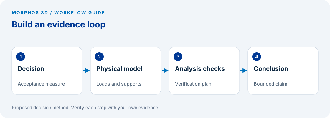
Describe how the real part is loaded and supported
List the applied actions and where they enter the component. Include the source of each load value, units and any uncertainty. Distinguish a measured condition from a design assumption so the analyst can see which inputs need confirmation.
Describe how the component is connected to the surrounding assembly and what movement those connections permit. A convenient restraint can make a model easier to solve while changing the physical question. Record the reasoning for each idealization instead of hiding it in the solver setup.
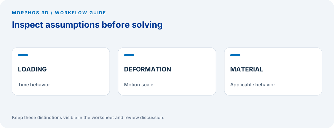
Include contact and material questions in the brief. If material behavior, separation, large motion or time-dependent loading could affect the result, ask the analyst whether the proposed study type represents those effects. Do not assume a particular package or solver covers them without checking the intended offering.
Check whether linear static assumptions fit
The official SOLIDWORKS explanation of linear static assumptions discusses slowly applied loads, small displacement and linear elastic behavior. Those are physical limitations to examine before treating a linear static result as an answer to the real problem. SOLIDWORKS assumptions of linear static analysis.
Use the assumptions as questions rather than as a checklist to approve automatically. If the event involves impact, a large change in shape or material behavior outside the intended model, document that concern and obtain an appropriate analysis approach. This article does not prescribe a solver or establish design safety.
Keep assumptions that cannot yet be verified visible in the result summary. A study can be useful for a bounded comparison while still being insufficient to approve a production design. State exactly which conclusion the evidence supports.
Put the method to work
Bring the design question, load information and the acceptance requirement you need to evaluate.
Use the worksheet belowPlan verification before interpreting the colors
Ask how the analyst will check that the model represents the intended question and that the numerical result is stable enough for the decision. The plan may include simplified calculations, sensitivity checks, mesh refinement and comparison with physical evidence, as appropriate to the problem.
Define the quantity being evaluated and where it will be assessed. An isolated displayed maximum is not automatically the governing acceptance measure. Have the analyst explain local effects, modeling choices and whether the chosen output is appropriate for the requirement.
Preserve the input configuration with the result. A plot without loads, supports, material assumptions and a model reference is difficult to review or reproduce. The brief should make it possible to connect the reported conclusion to the analysis that produced it.
Use the study to design the next evidence step
Record the result, its limitations and the decision it changes. If a load assumption dominates the outcome, the next useful action may be improving that input rather than refining the geometry. If the result is sensitive to a support idealization, examine the connection or test condition.
A first study may identify what a physical test needs to measure. It may also show that the original question requires a different analysis approach. Keep those outcomes distinct from a claim that the design has passed every requirement.
Bring the brief to a qualified technical discussion with the available geometry and supporting information. The goal is to agree on a defensible scope, the evidence needed and the person authorized to accept the engineering conclusion.
Checks to carry into the discussion
| Brief element | Question to answer | Evidence to attach |
|---|---|---|
| Decision | What will change because of the result? | Requirement and acceptance owner |
| Load case | What acts on the part, where and when? | Values, units and source |
| Supports and connections | What movement is physically constrained? | Assembly or test description |
| Material model | What behavior must be represented? | Applicable material information |
| Verification | How will the result be checked? | Analyst-agreed verification plan |
| Limitation | What does this study not establish? | Explicit unresolved assumptions |
Download the working worksheet
Complete the decision and input columns before asking for a simulation recommendation. Mark unavailable values as unknown rather than supplying convenient numbers. Keep units attached to every numerical input and retain the source of the value. Use the brief to agree on analysis scope with the appropriate specialist, then update it with the result and limitation. Do not treat completion of the worksheet as engineering approval.
Fields: Design reference · Decision · Acceptance measure · Acceptance owner · Load and units · Load source · Support assumption · Material information · Uncertainty · Proposed study checked by · Verification plan · Supported conclusion · Limitation.
The worksheet and decision method are original Morphos 3D guidance. Fill them with your own evidence; the file contains no customer data or assumed results.
Bring the design question, load information and the acceptance requirement you need to evaluate.
An attractive stress plot does not validate unsuitable physical assumptions.
Frequently asked questions
Should meshing be the first step?
First define the decision and physical assumptions. Mesh choices belong within an analysis and verification plan for that question.
Does a stress plot establish that a design is safe?
No. A conclusion depends on appropriate inputs, assumptions, numerical verification and the applicable acceptance requirements reviewed by the responsible technical authority.
Official references and method
References reviewed October 5, 2026. Product references support the specific capabilities discussed; the worksheets and decision steps are proposed guidance, not vendor benchmarks.
The linked help explains the underlying concept in the named documentation release. Confirm any setup procedure against the documentation for your installed version.
Discuss the next test
Bring the design question, load information and the acceptance requirement you need to evaluate.