
Track an Electrical-to-Mechanical Design Change
Control an electrical-to-mechanical design change with a shared change identifier, an impact register and acceptance by the responsible disciplines. Trace the change through schematics, component data, 3D layout and released manufacturing outputs before closing it.
Electrical and mechanical teams with a stated problem coordinating design changes.
Data synchronization alone cannot approve a component substitution.
Trace one electrical-to-mechanical design change
A component substitution can look complete in a schematic while leaving the mechanical layout and build information unchanged. Begin with one proposed change and identify every representation that may depend on it, rather than assuming the initiating discipline owns all of the consequences.
Assign a change identifier and state the reason for the change. Record the old and proposed component references, the affected assembly and the intended release. Keep the proposed state distinct from the currently approved build information.
Choose a representative case for the initial review. A connector change, device relocation or cable-route change can expose the handoff without requiring a redesign of the entire system. Use permitted project data and retain the actual engineering constraints instead of substituting a generic product demonstration.
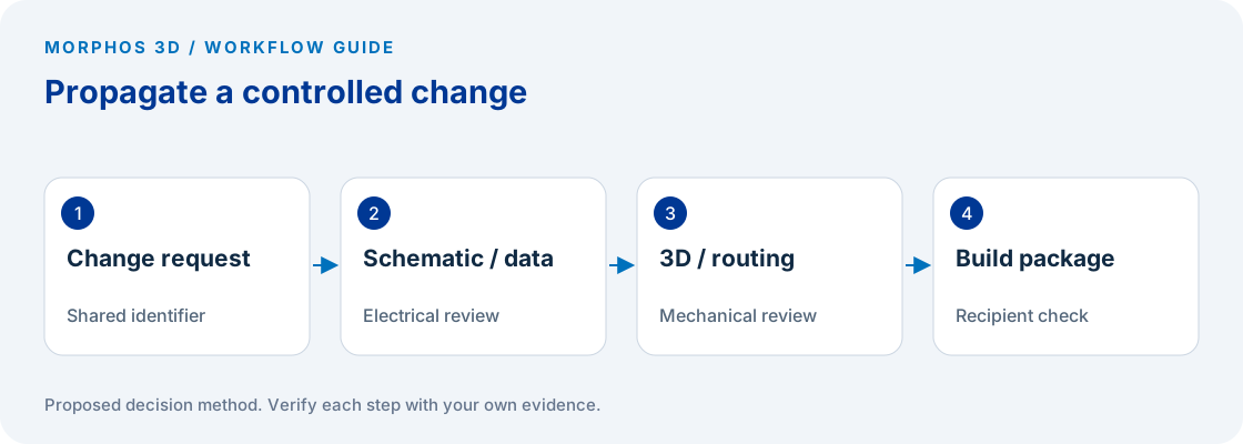
Build the impact register before updating documents
List the schematic, component record, mechanical envelope, connections, route and manufacturing outputs that may be affected. For each item, identify the responsible person and the acceptance evidence. Mark “no effect” only after the relevant owner has reviewed the change.
A replacement component can require more than a geometry update. The responsible engineers may need to inspect electrical ratings, terminal information, mounting conditions, access and assembly instructions. The applicable requirements come from the design and component documentation, not from this generic worksheet.
Avoid using one checked box to stand for every discipline. Mechanical fit, electrical suitability and release readiness are separate decisions. A change can satisfy one while leaving another unresolved.
Use integrated data without assuming automatic approval
SOLIDWORKS Electrical 3D connects electrical schematic information with the mechanical 3D design workflow. The official product description identifies coordination between the schematic and model environments. That connection can support the handoff, but it does not establish that a particular substitution has been approved for your design. SOLIDWORKS Electrical 3D.
Record which information is synchronized, which is generated, and which is maintained manually in the actual configuration. Ask the responsible users to demonstrate the change in their intended workflow and inspect the affected outputs. Keep edition, version and setup questions attached to the tested environment.
If the current process uses separate systems or manual exchange, the same impact register still applies. The immediate task is to preserve the relationship between the initiating change and every affected record, while making the remaining manual work visible.
Put the method to work
Bring one change that crossed electrical and mechanical ownership, including the downstream output.
Use the worksheet belowTest the handoff in both directions
For an electrically initiated change, have the mechanical owner inspect placement, mounting and route consequences that apply to the design. For a mechanically initiated relocation, have the electrical owner inspect the relevant connection and documentation consequences.
Record the response with the shared change identifier. A comment that only says “updated” does not reveal which representation was checked. Identify the document or model reference, the reviewed condition and any unresolved dependency.
Keep manufacturing in the loop when the change affects what is purchased, assembled, connected or inspected. Have the appropriate recipient identify the revised output they will use. This checks the delivered information rather than assuming that synchronized engineering data automatically produces a complete release package.
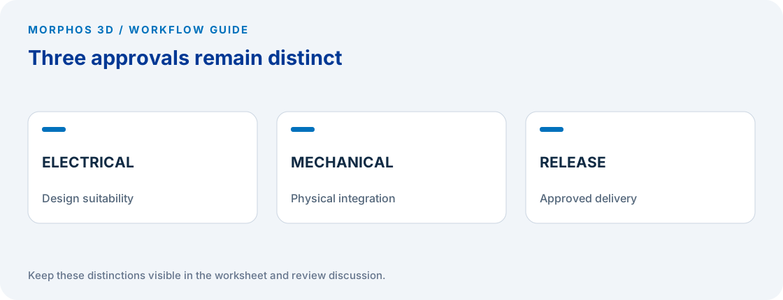
Close the change with evidence and remaining limits
Before closing the change, inspect the register for unassigned items, unchecked dependencies and conflicting release references. Require the responsible owners to resolve or explicitly disposition them through the established engineering process.
Record how superseded build information will be handled. A corrected schematic does not physically remove a previously issued drawing or instruction from another location. Distribution and withdrawal need an owner just as the design edit does.
Use the completed register to identify the recurring handoff problem. If component information is repeatedly missing, focus on that data responsibility. If changes are correct in engineering but unclear at assembly, focus on release and distribution. A targeted technical discussion can then start with an observed failure rather than a general request for better collaboration.
Checks to carry into the discussion
| Affected record | Responsible check | Acceptance evidence |
|---|---|---|
| Schematic | Connections and references reflect the intended change | Reviewed schematic reference |
| Component data | Required characteristics and identifiers are correct | Approved component record |
| Mechanical layout | Relevant fit, mounting and access are checked | Reviewed model reference |
| Routing | Applicable route and connection consequences are checked | Documented routing review |
| Build outputs | Purchasing and assembly receive the intended information | Recipient acceptance |
| Superseded package | Earlier information is handled by the release process | Distribution record |
Download the working worksheet
Use one row for each affected representation and keep the same change identifier across disciplines. Record an explicit rationale when an owner determines there is no effect. Do not include assumed electrical limits or clearances without the applicable design source. Review the register with the downstream recipient before closure, then retain it with the controlled change record. The worksheet organizes the handoff; it does not replace the required engineering approvals.
Fields: Change ID · Reason · Old reference · Proposed reference · Affected representation · Impact or no-effect rationale · Responsible discipline · Required check · Evidence reference · Open dependency · Release reference · Recipient acceptance.
The worksheet and decision method are original Morphos 3D guidance. Fill them with your own evidence; the file contains no customer data or assumed results.
Bring one change that crossed electrical and mechanical ownership, including the downstream output.
Data synchronization alone cannot approve a component substitution.
Frequently asked questions
Does synchronized data mean the change is approved?
No. Data coordination and engineering approval are different responsibilities. The applicable owners still need to accept the change and its downstream effects.
Can the register be used without integrated ECAD and MCAD tools?
Yes. It is a proposed method for recording affected representations, owners and evidence. Manual transfer steps should remain explicit so they can be checked.
Official references and method
References reviewed October 5, 2026. Product references support the specific capabilities discussed; the worksheets and decision steps are proposed guidance, not vendor benchmarks.
Discuss the next test
Bring one change that crossed electrical and mechanical ownership, including the downstream output.