SOLIDWORKS® Flow Simulation
Simulate airflow, liquid cooling, heat transfer, and pressure drop on your actual design model. No geometry export, no file conversion, no separate CFD tool to learn.
SOLIDWORKS Flow Simulation
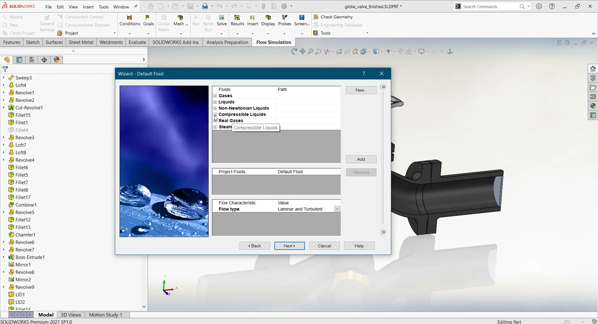
CFD embedded directly inside SOLIDWORKS — simulate liquid and gas flows, heat transfer, and pressure distribution on your live design model with no geometry export, no format translation, and no separate CFD tool. Optional Electronics Cooling and HVAC modules extend the base product.
 Morphos 3D is an authorized SOLIDWORKS reseller. We help teams configure flow studies for thermal management and cooling validation.
SOLIDWORKS Flow Simulation Packages
Start with the base Flow Simulation product and add modules for specialized applications. All packages run inside SOLIDWORKS on your existing model.
Compare Packages
Full range of liquid and gas flow simulation, heat transfer, and parametric optimization. Handles internal and external flow, rotating regions, free surfaces, and porous media.
- Compressible and incompressible flow
- Internal and external flow scenarios
- Conjugate heat transfer (fluid-solid)
- Gravity, rotation, and free surface effects
- Parametric "what-if" optimization studies
- Customizable engineering materials database
- Results visualization and reporting tools
Adds radiation, semitransparent materials, thermal comfort analysis, and tracer studies for occupied spaces.
- All base Flow Simulation capabilities
- Semitransparent material radiation modeling
- Thermal comfort factor analysis
- Tracer study for air quality and containment
- HVAC component engineering database
Component-level thermal models: Joule heating, heat pipes, thermoelectric coolers, two-resistor IC models, and PCB layer properties.
- All base Flow Simulation capabilities
- Heat pipes and thermal joints
- Thermoelectric coolers (TEC) simulation
- Two-resistor component models for ICs
- Joule heating for conductors
- PCB lay-up thermal modeling
What You Can Do with SOLIDWORKS Flow Simulation
Run CFD on your live SOLIDWORKS model — same geometry, same interface. When the design changes, re-run, not re-build.
- Fully embedded — no geometry export or translation
- Uses SOLIDWORKS materials and configurations automatically
- Same UI paradigms as SOLIDWORKS: toolbars, right-click menus, PropertyManager
- Runs parametric studies on design configurations in one setup
- Results appear as color-mapped plots directly on the 3D model

Component-level thermal accuracy for PCBs and enclosures — two-resistor IC models, heat pipes, TEC simulation, Joule heating, and PCB layer thermal properties.
- Two-resistor component models for IC packages
- Heat pipe simulation including evaporator and condenser behavior
- Thermoelectric cooler (Peltier device) modeling
- Joule heating in copper traces and conductors
- PCB lay-up thermal properties by layer
- Thermal joint resistance between components and heatsinks
Setting Up Flow Studies for Thermal and Cooling Validation
SOLIDWORKS Flow Simulation is accessible, but setting up a valid study — one that actually predicts real-world behavior — requires understanding boundary conditions, mesh settings, and convergence criteria. We help your team get there faster.
Our focus is thermal management and cooling validation: electronics enclosures, cooling channel design, and heat transfer studies. We configure the study setup, validate boundary conditions against physical measurements where possible, and walk your engineers through interpreting results they can act on.
- Study setup and boundary condition review for your application
- Mesh refinement guidance for accuracy vs. solve time trade-offs
- Training on results interpretation: reading plots, extracting values, generating reports
- Module recommendation: base product vs. Electronics Cooling vs. HVAC
- Ongoing support for new study types as your product line evolves
- ✓ Electronics enclosure natural and forced convection cooling
- ✓ Cooling channel pressure drop and flow distribution
- ✓ Heat exchanger effectiveness studies
- ✓ Parametric studies comparing cooling fin geometries
- ✓ Fan selection and airflow rate validation